In Short
The compressor start / stall / knocking noise test system (in short CSTS) is used to evaluate a number of different compressor characteristics. The test rig is designed to handle standard compressors (typically driven by an induction electric motor) or variable capacity compressors (of e.g.the brushless DC types) using a variety of inverters. The system can automatically perform start, stall and knocking noise tests while the compressor is exposed to a large field of suction and discharge pressures, suction gas temperatures, ambient temperatures, voltages and winding temperatures.
Introduction
Start characteristics
Whether a compressor can start with given low and high side pressures depends on the compressor design itself and a large number of parameters. At compressor start the electrical motor has to deliver sufficient torque to allow the rotor to start rotating and, for reciprocating compressors, compress the gas in the cylinder and press it through discharge ports and mufflers into the high pressure line. The principle start characteristics are therefore defined by electric motor design and the required start torque for the compressor module.
The CSTS system allows to expose the compressor to a large range of suction and discharge pressures and evaluate whether the compressor is able to start up. In addition suction gas temperature, room temperature and also compressor winding temperatures can all be set. The latter is organized by running a preheating phase prior to the compressor start. The start performance is also affected by the voltage given to the electrical motor. Therefore also this parameter can be varied or it can be chosen to automatically search for the minimum voltage at which the compressor starts, keeping all other parameters constant.
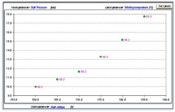
The result of a series of start tests can be compiled in a map where e.g. the minimum start voltage is plotted against suction and discharge pressure (for convenience often expressed in their saturation temperatures).
Stall characteristics
Once a compressor is started up it can be run until a maximum load condition at which the electric motor is not able to rotate the rotor any more. This is called the stall point and can generally be achieved by e.g. continuously increasing the discharge pressure. Also this stall point depends on compressor and motor design.
The CSTS system can expose the compressor to a range of suction pressures and for each of these let the compressor run against an increasing discharge pressure until the stall point is achieved, or until a maximum predefined pressure level is reached. This test can again be performed at varying voltages, suction gas conditions, room temperatures and compressor winding temperatures.
Knocking noise characteristics
When a compressor starts or stops, it is possible that specific sound effects may occur, known as knocking noises. These effects can occur at specific pressure conditions at which the compressor is started or stopped.
The CSTS system can run the compressor to various suction and discharge pressure settings after which the compressor is stopped. It requires an operator to register the noise at such event. The compressor is subsequently started again while again the noise can be registered, so start and stop knocking noises can be tested. This process is typically repeated a number of times.
Main characterisitics
A short summary of the main characteristics of the system:
- Refrigerants: R-134a, R-600a, R-290, mixtures of R-290 and R-600a
- Single speed and variable speed compressors
- Compressor input power measurement. For variable speed compressors also the power in between inverter and compressor is measured, also giving the rotational speed.
- Oil separator: An oil separator is mounted in the discharge line, automatic oil return to compressor, oil separator can be bypassed.
- Compressor ambient temperature control with an air speed <0.2 m/s (natural convection)
- Compressor power supply: single phase AC source 0-300Vac, 15Hz-1kHz, 2000VA
- Winding temperature measurement and control: For standard compressors, by placing a DC voltage (20V) on the coil which can be done during compressor run. For VCC compressors, the compressor is momentarily stopped and the resistance is measured using a resistance measurement
- Compressor ambient temperature control: 10 to 60°C
- Suction gas temperature control: 0 to 60°C
- Temperature controlled PTC box: in order to quickly perform multiple start tests on the same compressor sample, a box is present in which 8 PTC’s (electrical compressor connections) can be installed, the system automatically switch between PTC’s in order to start the compressor every time with a cold PTC.
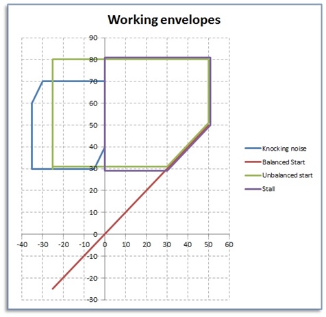
- The diagram on the next page presents the working envelop for the different tests. The X-axis represent the saturation temperature of the suction pressure, the Y-axis the saturation temperature of the discharge pressure.
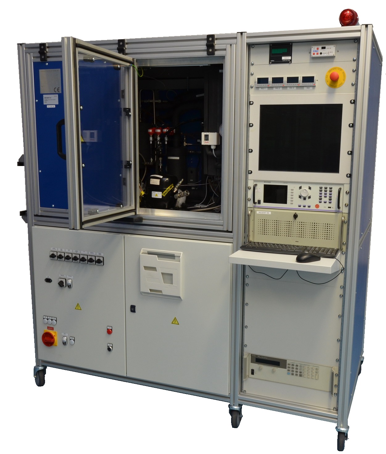
Basic system layout
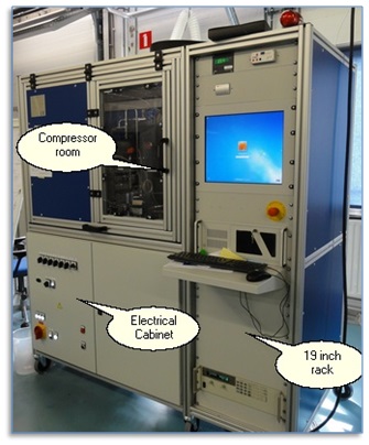
- Compressor room: Contains the compressor to be tested. This room, which is sealed (when the door is closed) contains the primary refrigeration circuit. For safety purposes there are no refrigerant lines outside of this room. The exceptions are the refrigerant line to the evacuation pump and the refrigerant venting line. Both are sealed off by means of valves. The room is protected via a gas sensor and continuous ventilation.
- Electrical cabinet: Contains the main part of the data acquisition system and the majority of the electrical components like relays, circuit breakers etc.
- The 19 inch rack: Contains the following components:
- Gas transmitter: to detect leakage of flammable refrigerant in the compressor room
- Vacuum pump display
- Automatic expansion valves controllers
- Computer screen
- Optional LMG 500 power analyzer
- Computer
- Writing desk with keyboard and mouse
- Free space (possible position for alternative computer or any additional components)
- Power source
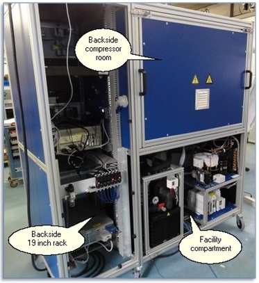
- Backside compressor room: Contains the fans, electrical heater and cooling coil to control the temperature in the compressor room. Next to this also the flammable gas sensor is positioned here.
- Facility compartment:
- Water chiller unit: Provides temperature conditioned water for the vessel in the the compressor room.
- Room cooling system: Provides cooling to facilitate the cooling coil in the backside compressor room.
- Ventilation: The ventilation channel with ventilation sensor and ventilation control valve.
- Evacuation unit.
- Backside 19 inch rack:
- Pneumatic equipment to operate the ball valves.
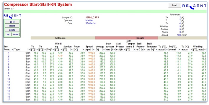
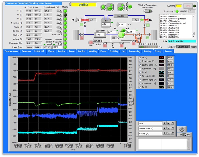
Control software
The next figure shows an example of the control software
Evaluation software
The next figures show an example of the evaluation software