Introduction compressor calorimeter
In order to quantify the performance of hermetic compressors, RE/GENT developed several compressor calorimeter types, initially for its own use, but since 15 years also as a product delivered to customers. The calorimeters are completely designed and constructed by Re/genT and include state of the art measurement equipment, data acquisition and control systems and operating software.
Calorimeters of Re/genT excel in accuracy and usage convenience. The calorimeters are fully automatic meaning that the operator only has to install the compressor (suction and discharge connection and electrical connections) and enter the field of operating conditions.
The calorimeter then fully automatically evacuates the compressor, performs a leakage test, starts the compressor and runs through the complete field of operating conditions without any user intervention. All operating conditions are fully automatically controlled over a wide range:
- Evaporation pressure
- Condensation pressure
- Subcooling temperature
- Superheating temperature
- Suction gas temperature
- Compressor ambient temperature
- Compressor supply voltage and frequency
- Compressor speed (for variable speed compressors)
The calorimeters have specifically been designed for engineering purposes, allowing the use of various refrigerants, including flammables. With respect to the latter, the low refrigerant charge of the system is relevant. In addition refrigerant mixtures can be handled (such as hydrocarbon mixtures, R-404A etc.). The calorimeter is suitable for compressor research tasks / prototype testing due to very high accuracy and stability settings possible. Next to this the calorimeter comes with very extensive software with detailed analysis functionality. Next to this, the calorimeter is also suitable for production control. Due to its extremely fast stabilization time (normally within a couple of minutes after starting a compressor all parameters are stabil) many compressor samples per day can be tested.
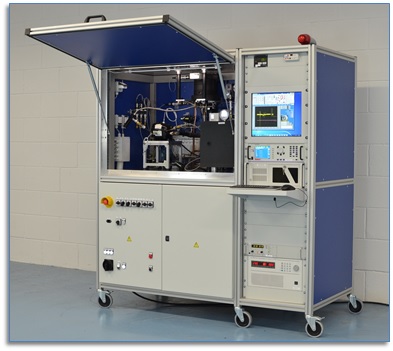
Compressor calorimeter examples: Fully automatic double compressor calorimeter
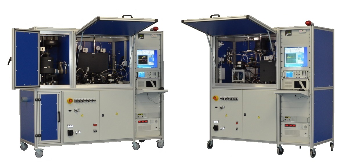
The next pictures show an example of the fully automatic double compressor calorimeter, which is suitable for installing 2 compressors that are fully automatically evacuated, leak tested and tested over a wide range of operating conditions in series. The cooling capacity range for the model shown is 40..600 Watt (higher and lower cooling capacities also possible for this model).
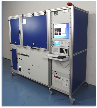
Temperature controlled calorimeter vessel room (also containing condenser, accumulator, subcoolers, mass flow meter etc.).
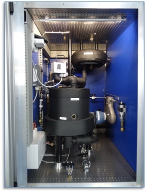
Temperature controlled compressor room (2 compressor positions).
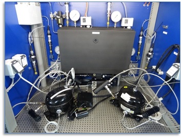
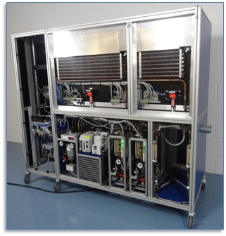
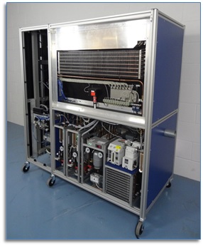
Calorimeter backside (panels removed) with integrated chiller unit, water conditioners and evacuation pump.
Compressor calorimeter examples: Fully automatic single compressor calorimeter
The next pictures show an example of the fully automatic single compressor calorimeter. After mounting the compressor with quick connectors it is fully automatically evacuated, leak tested and tested over a wide range of operating conditions. The cooling capacity range for the model shown is 20..600 Watt (higher and lower cooling capacities also possible for this model).
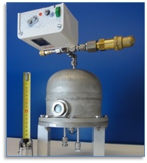
Extremely small calorimeter vessel (height only 14cm). This calorimeter vessel has the expansion device positioned inside to prevent any errors due to heat loss. Due to the small design the heat losses are extremely small, which results in a very high accuracy. Next to this, due to the low weight, the stabilization time is very fast.
Temperature controlled compressor room, containing the complete refrigerant circuit.
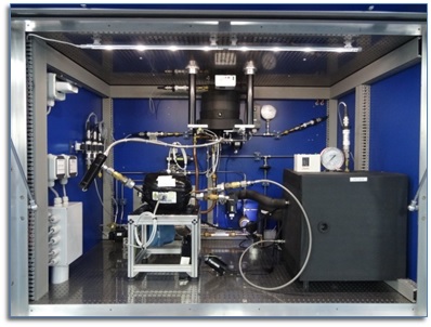
Temperature controlled compressor room, containing the complete refrigerant circuit.
Main features of the compressor calorimeters:
- 3 Years ago Re/genT researched a compressor calorimeter design suitable to measure cooling capacities down to 5 W (required for extremely low capacity variable speed compressors running at minimum speed and low evaporation temperatures). For conventional compressor calorimeters, stability, stabilization time and accuracy become worse when going to lower cooling capacities (e.g. lower than 50 to 100W). Many techniques and components developed for the 5W compressor calorimeter are also applied in the compressor calorimeters suitable to measure up to 600 Watt cooling capacity. This results in high stability, short stabilization time and extremely high accuracy over the complete cooling capacity range.
- For all calorimeter models the principal method of the compressor cooling capacity measurement is by evaporation of a secondary refrigerant in a vessel (method A in EN13771-1), which exchanges the heat with an evaporator coil in the primary refrigeration circuit. The expansion device is installed inside the vessel to avoid any heat losses of this device and therefore errors in the measurement.
- The conforming method is by means of a Coriolis mass flow meter applied in the liquid line of the refrigeration circuit (method E in EN13771-1); the deviation between the two methods is generally smaller than 1 %.
- Handling of many refrigerants, such as R134a, R600a, R-290, Care30, R404a, R407C, R1234yf/ze, R441A,
- Measurements according to EN 13771-1, EN 12900, ISO 917, GB/T 9098, ASHRAE 23 and CECOMAF standards.
- Combined vessel and compressor room, which is temperature controlled for the single compressor calorimeters.
- Separate vessel and compressor room, which are temperature controlled for double compressor calorimeters.
- Exact control of condensation temperature (discharge pressure), evaporation temperature (suction pressure), refrigerant liquid subcooling, vapour superheating, compressor suction temperature, compressor ambient temperature, compressor power supply, compressor speed etc.
- An oil separator is included, which can also be bypassed.
- Integrated chiller unit.
- Safe design, main characteristic is the low refrigerant charge (max 130 / 210 gram of hydrocarbons for respectively the single and double compressor calorimeter) in combination with a safety system using a flammable gas sensor and continuous ventilation.
- Automatic test sequencing, resulting in complete compressor maps.
- Control and measurement is based on Labview software with National Instruments data acquisition and control hardware.
- All communication between sensors and measurement system is digital (this prevents noise and loss of accuracy due to analogue signals).
- Real time performance calculations, data acquisition and data display (using only software PID controllers).
- Final reports (including compressor maps and diagrams) are generated in Microsoft Excel.
- Wide variety in operating conditions possible, including evaporation and condensation temperatures, subcooling and superheating temperatures, environment temperatures, voltage and frequency supply, compressor speed control etc.
- Compressors can be tested using natural convection or fan cooling.
- Integrated explosion proof evacuation pump with high accuracy vacuum sensor.
- High accuracy inverter energy consumption measurement.
- Variable speed compressor control via TTL signal (square, sine, or triangle wave can be selected with variable frequency 10..400 Hz and variable amplitude 0-10 V) and/or digital communication
- Refrigerant circuit build with stainless steel tubing, Stainless steel Swagelok connections and fully automatic pneumatically operated Swagelok ball-valves.
- Design is based on more than 30 years of experience with compressor calorimeters.
Optional:
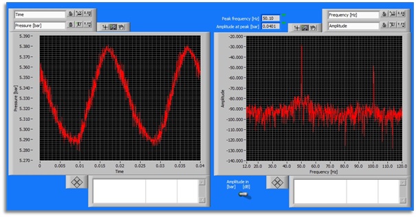
- Discharge pressure pulsation measurement (with determination of rotational speed).
- High speed compressor input current measurement (with determination of rotational speed for normal compressors)
- Compressor winding resistance measurement for single speed compressors during compressor run
- Compressor winding resistance measurement for variable speed compressors (automatically after each test condition the compressor is shortly stopped and restarted for this purpose).
Any other specific additional options can be discussed.
Calorimeter control software
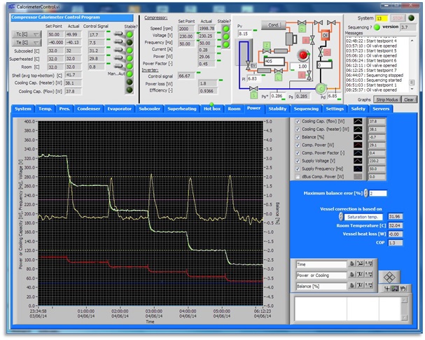
The next figure shows an example of the calorimeter control software. In the sheet displayed the compressor input power, cooling capacity (measured by mass flow meter and by calorimeter vessel) and balance are shown for 6 different test conditions.
The next figure shows an example of the fast discharge pressure measurement, with on the right side the frequency analysis from which the compressor rotational speed can be determined.
Calorimeter evaluation software
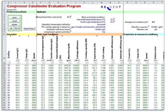
The next figure shows part of the data point overview from the test results evaluation program.
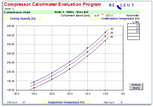
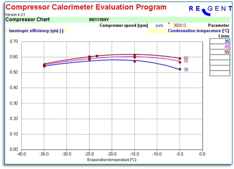
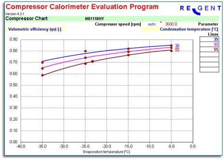
The next figures show some examples of the test data evaluation software:
- Cooling capacity as function of the evaporation temperature at three different condensation temperatures. The red points are the exact results of the measurement points, the lines are generated by the regression model in the evaluation software.
- Isentropic efficiency graph
- Volumetric efficiency graph
In the same way graphs of the compressor input power, COP, shell temperature, discharge temperature etc. are available.
