
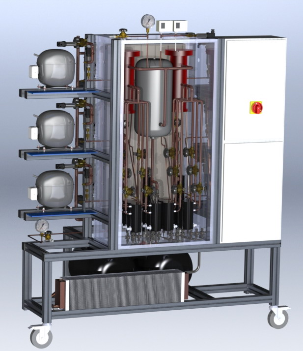
Main features
- The system has 12 compressor positions.
- All 12 compressors are operating (on/off) in parallel on 1 gas loop
- Normally 6 indentical compressors (of the same type) are installed on the left side of the system and 6 compressors of another type on the right side.
- The system synchronizes the on-phases of the A-type and B-type compressors in such a way that the total gas flow through the single gas loop (by the 12 compressors) is more or less constant.
- To dampen out remaining pressure fluctuations, large suction and discharge side volumes (gas-vessels) are applied.
- The discharge pressure of the system (of the 12 compressors) is controlled using an automatic gas-expansion valve (in fact two valves with different flow ranges are applied for this purpose). The setpoint for the discharge pressure can be set in the software by the operator. Discharge pressure range (saturation temperature) = 35 to 55°C
- The suction pressure depends on the total refrigerant charge applied to the system. (at the beginning of the tests, the system needs to be charged with a certain amount of refrigerant, obtaining the desired suction pressure). Suction pressure range (saturation temperature) = -30 to +10°C
- For each compressor a manual Danfoss suction (VS) and discharge (VD) valve is present to be able to remove the compressor from the system without interrupting the tests.
- For each compressor an oil separator is present and oil return to the compressor is assured.
- To avoid condensation of refrigerant on the discharge side, the oil separators, discharge tubes, oil accumulators and discharge vessel are placed in a “Hot box”, which is controlled at approximately 70°C.
- After the expansion valves, the refrigerant flows through a heat exchanger with air (gas cooler) in order to cool down to approximately the ambient temperature before entering the compressors again.
- The compressors themselves are placed on an open platform (the compressor ambient temperature therefore will approximately be the ambient temperature of the laboratory in which the system is positioned).
- The system only contains 1 main suction and 1 main discharge pressure sensor. Due to the design and tube diameters chosen, these sensors will accurately present the suction and discharge pressures for all 12 compressors.
- The system is suitable for R600a as well as R134a
- The total maximum (flammable) refrigerant content of the system is 1 kg. The system itself is protected in the following way:
- All electrical components that could come into contact with leaked flammable refrigerant are ATEX certified (explosion proof).
- The complete electrical cabinet is sealed to at least IP54.
- The system contains 2 temperature sensor (thermocouples) per compressor + in total 6 extra temperature sensors are available, further the ambient temperature and hot box temperature are measured.
- For each compressor the electrical input current (input to inverter) will be measured.
- For each compressor a square wave 5V frequency signal will be available to control the compressor speed (compressors can be started either by power supply or by frequency signal).
- Optionally, for each compressor also a USB connection is available, to be used for a USB-Dbus converter to control the compressor speed.
- A computer with data acquisition system will be applied to control the system and monitor the data:
- The system has the option to automatically continue testing after a complete system shut down.
- Software:
- Measurement and control software in Labview.
- Evaluation software in MS. Excel.
- Further the system contains the following additional components:
- A manometer on suction and discharge side.
- Double discharge pressure protection.
- A switch to select the compressor power supply. The actual power supplied (voltage / frequency) is not monitored.
- The following laboratory requirements apply:
- Electrical power supply: Single phase 220/240V, 50 Hz, 25 A
- Compressor power supply: The system itself does not contain a stabilized power source for compressor power supply, instead it has 3 input lines for laboratory power supply (e.g. 230V 50Hz, 230V 60Hz, 115V 60Hz)
- Laboratory room temperature range: max 35°C
- MS Office license
- Safety system: The room in which the system is positioned should have continuous ventilation to the ambient (to the outside of the building). A gas sensor should be present in the room, which interrupts the power supply to the complete system in case of detection of flammable refrigerant.
- The compressor power supply socket, frequency control signal connector and USB connector for USB-Dbus converter are available next to each individual compressor
- A shelf is installed next to each compressor to position the inverter and / or dbus converter.

Measurement and control software
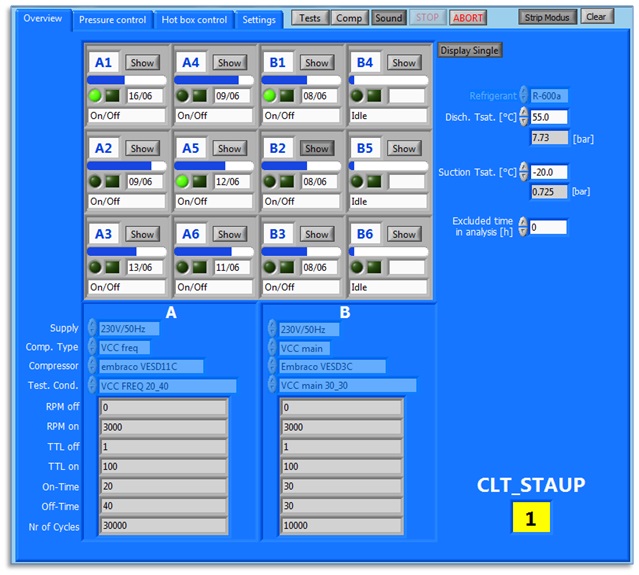
The next figure shows the main overview sheet of the control program. On the right side it shows the setpoints given for the suction and discharge pressure (identical for all 12 compressors). For each individual compressor a short overview is given indicating the test progress (slide bar) and the expected end date of the test. Further is shows if the compressor is running (round LED) and if there is an alarm (square LED).
At the bottom, the exact test conditions for the A and B type compressor are indicated.
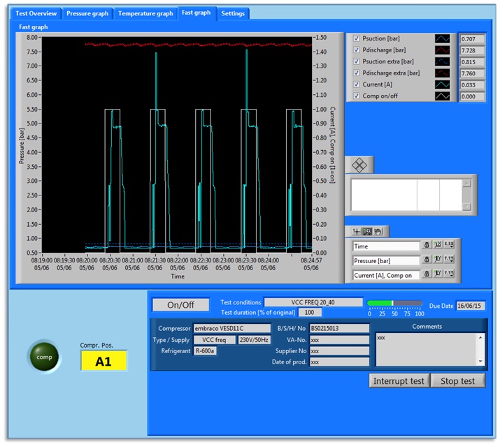
When pressing the “show” button for an individual compressor (see overview sheet above) a separate program is shown that displays the detailed data for 1 single compressor sample being tested.
The figure on the next page shows 1 sheet from this program (the so-called “fast-graph”). In this “fast graph” the following is displayed:
- With a white line it is indicated whether the compressor is powered or not (this can be either the main power supply to the inverter that is turned on/off or the frequency control signal that is put on a low (e.g. 1 Hz) or high (e.g. 100 Hz) value
- The light-blue line shows the compressor input power. This line shows the starting behavior (starting delay etc.) of the compressor.
- The dark-blue line shows the suction pressure.
- The red line shows the discharge pressure.
Evaluation software
The control software automatically stores a data file during testing for each compressor sample. This data file can easily be loaded into an excel database in which all main results of the tests can be evaluated.
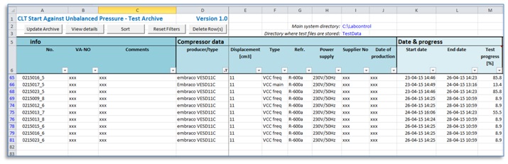
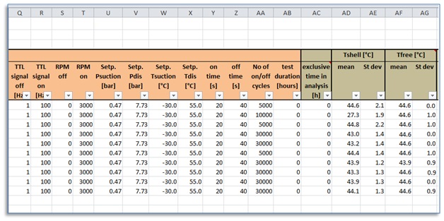
In this database also individual tests can be selected of which than a detailed graph is presented. Finally also an automatic test report of for example 6 compressor samples can be generated showing the main results ans whether this specific type of compressor passed or failed the tests.